Будущим поколениям наставление от потерявшего три дня )))
Компилятор Баском-51 тупо-умный компилятор!
У меня привычка делать DAT-файл индивидуально под конкретный МК. Да, долго и муторно, вручную выписывать все регистры, прерывания и прочее, но это надёжно.
А тут я поленился и пошел по пути китайских демо-программок: один файл на всё семейство.
Пишу-пишу - не работают мои программы! Три дня так... Потом думаю: А вообще, ножкодрык на этом пине работает?
А не работает! Беру другой МК, который точно не трогал - не работает!
Оказывается этот хитрый Баском-51 делает всё как я сказал, плюс меня перестраховывает 
...
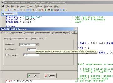
Например, у меня в DAT-файле указано прерывание с адресом D0, и ниже указано начало кода пользователя ORG = DE
В ассм он выдаёт org = D0, но таблица прерываний-то идёт ниже, включая DE! и программы не работают!
Надо ручками сделать файл и после указать ORG = адр последнего прерывания + 3. Тогда всё OK 
PS!
и, конечно же, это есть в Справке ))
Making your own register file is very simple:
· copy the 8052.DAT file to a new DAT file for example myproc.DAT
DOS c:\bascom copy 8052.dat myproc.dat
· edit the registerfile with BASCOM
A register file has a few sections. The following example shows only a few items under each section.
The [BIT] section contains all SFR's which are bit addressable. A bit addressable SFR ends with 0 or 8.
After the SFR name you can write the hexadecimal address.
An optional initial value for the simulator can also be specified. Separate the values by a comma.
Acc = E0 , 00
The [BYTE] section contains all the other SFR's.
The [MISC] section has a few items:
· up : here you can enter a short name for the uP.
· IRAM : the amount of available internal memory (128 or 256 bytes)
· org : the hexadecimal address where the code can start. This is 3 bytes after the last interrupt entry address, because the last interrupt will have a LJMP to an ISR and a LJMP needs 3 bytes.
· I_xxx : where xxx is the name of the additional interrupt. The name must be no longer than 6 characters. As you can see in the example below the last interrupt T2 has an entry address of 73 (hex). So the org is set to 73+3 = 76 (hex).
You only need to specify the additional interrupts. The interrupts for INT0,INT1, TIMER0, TIMER1 and SERIAL are already handled by the compiler.
· CLOCKDIV : The division factor of the oscillator. By default this is 12 and when you don't specify it, 12 will be used. Some micro processors have a division factor of 6 or 4.


